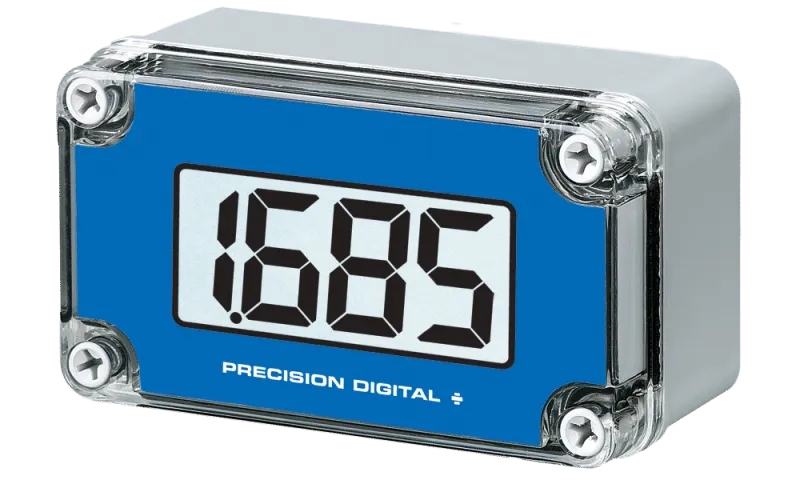
The Precision Digital PD685 is a reliable digital indicator designed for hazardous environments. It meets ATEX and IECEx safety standards and is rated IP67 for water and dust resistance. This loop-powered device is simple to install and program, making it a great choice for various applications.
One of the standout features of the PD685 is its visibility. Whether in bright sunlight or low-light conditions, the display remains clear, especially when the backlight is turned on. This ensures you can read measurements from a distance without any hassle.
Since the PD685 is loop-powered, there’s no need to install extra power lines in hazardous areas, saving you time and money. It draws all the power it needs from the 4-20 mA loop, with a minimal voltage drop of just 1 V (or 4 V with the backlight). This design keeps the burden on the loop low.
With an impressive operating temperature range of -40°C to +75°C, this meter is built to perform in extreme conditions. Installation is straightforward, thanks to a 22 mm (0.865″) conduit hole that can be placed wherever you need it.
Calibration is quick and easy, requiring only a simple two-step process. You’ll adjust two sets of coarse and fine potentiometers, which do not interfere with each other, making it user-friendly.
- Brand: Precision Digital
- Material: Durable, weather-resistant casing
- Age: Suitable for industrial use
- Size: 22 mm conduit hole for easy installation
- Use Case: Ideal for hazardous environments
- Operating Temperature: -40°C to +75°C
- Power: Loop-powered, no additional power lines needed
- Visibility: Clear display in bright sunlight and dim light
- Calibration: Simple two-step process
Choose the Precision Digital PD685 for a dependable, easy-to-use digital indicator that excels in challenging environments.
General
Except where noted all specifications apply to operation at +25°C.
Input: 4-20 mA @ 30 VDC maximum
Display: 28 mm (1.1″) LCD, 3½ digits; -1999 to +1999
Backlight: Powered by 4-20 mA loop. Intensity varies with signal level
Accuracy: ±0.1% FS ±1 count
Entity Parameters: Ui = 30 V, Ii = 175 mA, Pi = 1 W, Ci = 0, Li = 0
Decimal Point: User selectable via J2 jumper
Calibration: Four-step coarse and fine control; non-interacting zero and span
Calibration Range: 4 mA input: -1000 to +1000; 20 mA input: between 20 and 2000 counts > 4 mA display
Display Update Rate: 2.5/second
Maximum Input Current: 30 mA
Input Overload Protection: Over voltage protection to 30 V max (between S+ and S-)
Maximum Voltage Drop: 1 V @ 20 mA (4 V @ 20 mA with backlight)
Operating Temperature: -40°C to +75°C
Storage Temperature: -40°C to +85°C
Relative Humidity: 0 to 90% non-condensing. Printed circuit boards are conformally coated.
Enclosure: Impact-resistant, glass-filled, polycarbonate body, opaque; Impact-resistant, polycarbonate cover, transparent; Polyurethane/polymer gasket; Polyamide/plastic cover screws; NEMA 4X, IP67
Connections: Removable screw terminal block, 12 to 24 AWG.
Conduit Hole: One 22 mm (0.865″) conduit hole may be provided; refer to Ordering Information to specify conduit size and hole location; request sku (-Z) for no conduit hole.
Weight: 340 g (12 oz)
Warranty: 2 years parts & labor
Compliance Information
Product Markings:
0518 |
II 1 GD |
Ex ia IIC T4 Ga |
Ex ia IIIC T135°C Da |
-40°C ≤ Ta ≤ +75°C; IP67 |
Special Conditions for Safe Use:
- The permitted ambient temperature range for the PD685 is -40°C to +75°C (-40°F to 167°F).
- Use suitably certified and dimensioned cable entry device and/or plug. The equipment shall be installed such that the supply cable is protected from mechanical damage. The cable shall not be subjected to tension or torque.
- Under certain extreme circumstances, the non-metallic parts incorporated in the enclosure of this equipment may generate an ignition-capable level of electrostatic charge. Therefore, the equipment shall not be installed in a location where the external conditions are conducive to the build-up of electrostatic charge on such surfaces. This is particularly important if the equipment is installed in a zone 0 location. In addition, the equipment shall only be cleaned with a damp cloth.
- The cable entry into the enclosure shall be by means of conduit or cable gland and shall provide a minimum degree of protection of IP5X.
Year of Construction: This information is contained within the serial number with the first four digits representing the year and month in the YYMM format.
For European Community: The PD685 must be installed in accordance with the Essential Health & Safety Requirements of Directive 2014/34/EU, the product certificates CML 17ATEX2113X and IECEx CML 17.0052X, and the product manual. All controls and wiring connectors are accessed by opening the enclosure. To access electrical connectors, remove the enclosure cover, unscrew the two captive screws that fasten the printed circuit board, and remove the printed circuit board from the enclosure.
Connections

Figure 1: Calibrator Connection
Figure 2: Calibration Controls Location
Two-Wire Transmitter Input
Figure 3: Control Loop Connections (2-Wire)
Figure 4: Control Loop Connections with Backlight (2-Wire)
Four-Wire Transmitter Input
Figure 5: Control Loop Connections (4-Wire)
Figure 6: Control Loop Connections with Backlight (4-Wire)
Dimensions and Wall Mounting
A: 80 mm (3.15″) | C: 62 mm (2.44″) | E: 70 mm (2.75″) |
B: 130 mm (5.12″) | D: 112 mm (4.41″) | F: 20 mm (0.79″) |
Pipe Mounting Kit
The PDA6845 is a pipe mounting kit with two mounting holes. It provides all of the necessary hardware to mount the PD685 to a 2″ pipe. It is available in zinc plated and stainless steel materials.

Panel Mounting Kit
The PDA6854 is a panel mounting kit for the PD685. It provides all of the necessary hardware to mount the PD685 meter to an equipment panel. This panel mounting kit is not intended to provide waterproof protection to the panel.
