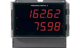

The Precision Digital PD6622 Loop Leader is a loop-powered 1/8 DIN digital flow rate and totalizer meter that provides simultaneous display of flow rate and accumulated total from a 4–20 mA input signal—without the need for an external power supply.
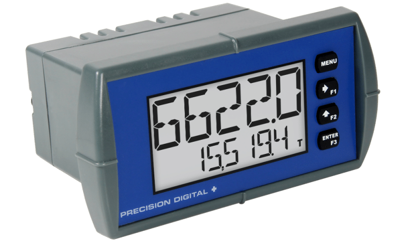
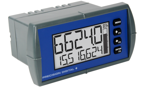
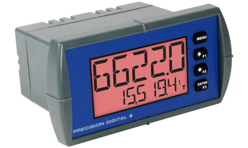
Designed for clear and reliable local indication, the PD6622 features a dual-line LCD display with a 5-digit alphanumeric upper display and an 8-digit alphanumeric lower display. Users can configure the display to show flow rate, total, grand total, engineering units, tags, or custom messages for enhanced operational flexibility.
Ideal for flow monitoring applications, the PD6622 combines a compact panel-mounted design with a rugged Type 4X / NEMA 4X / IP65 front panel, making it suitable for harsh industrial environments. Its two-color backlit display ensures excellent readability under various lighting conditions.
Configuration is quick and convenient through the built-in Micro USB port using Precision Digital’s free MeterView XL software. The meter is supplied standard with two open-collector outputs and one digital input, while optional models offer two solid-state relays and an isolated 4–20 mA retransmission output for advanced control and monitoring functions.
For added confidence in industrial installations, the PD6622 is UL and C-UL 61010 listed, meeting recognized electrical safety standards.