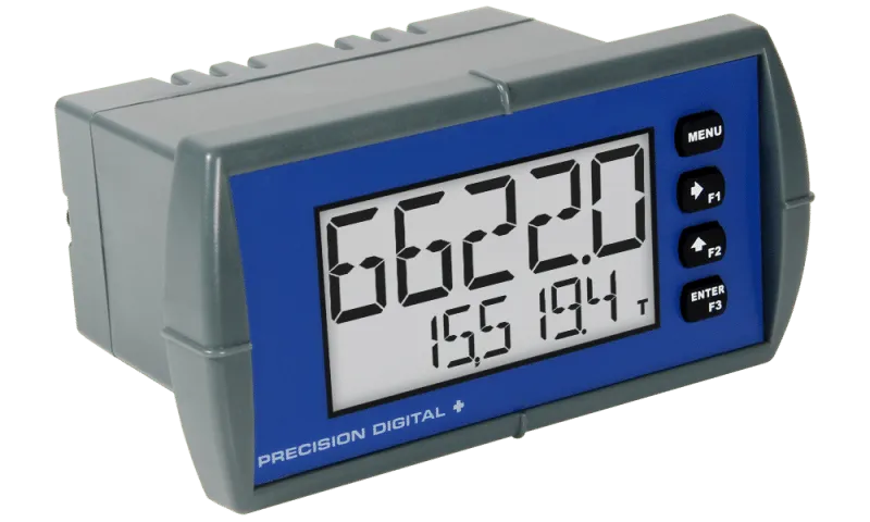
The Precision Digital PD6626 Loop Leader is an intrinsically safe, nonincendive, loop-powered 1/8 DIN digital flow rate and totalizer meter designed specifically for hazardous area applications. It provides simultaneous display of flow rate and accumulated total directly from a 4–20 mA input signal, eliminating the need for an external power supply.
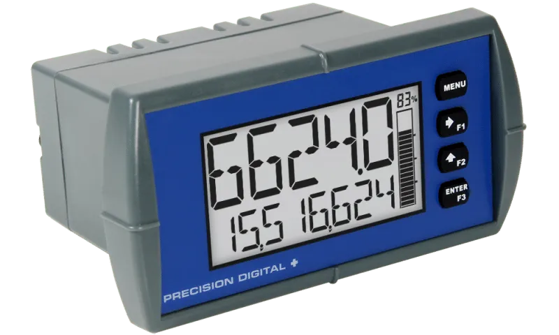
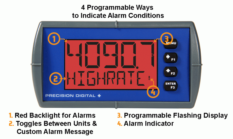
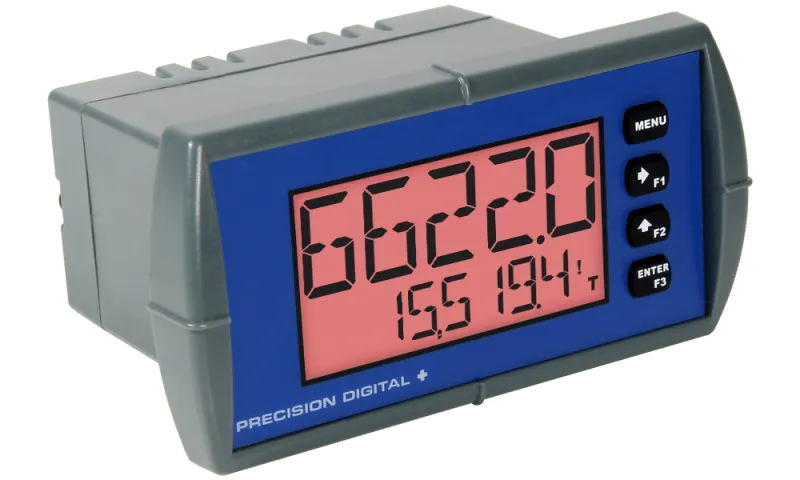
The meter features a dual-line LCD display with a 5-digit alphanumeric upper display and an 8-digit alphanumeric lower display. Users can configure the display to show flow rate, total, grand total, engineering units, custom tags, or personalized messages for enhanced operational flexibility.
Engineered for use in hazardous environments, the PD6626 offers clear local indication of process data while maintaining a compact panel-mounted design. Its rugged Type 4X / NEMA 4X / IP65 front panel and two-color backlight ensure excellent visibility and durability in demanding industrial conditions.
Configuration and setup are simplified through the built-in Micro USB port and free MeterView XL software. Standard features include two open-collector outputs and one digital input, while optional models are available with two solid-state relays and an isolated 4–20 mA retransmission output for advanced monitoring and control applications.
For maximum safety and compliance, the PD6626 is UL and C-UL listed as Intrinsically Safe and Nonincendive, and is also certified to ATEX and IECEx Intrinsically Safe standards, making it an ideal solution for flow monitoring in oil & gas, chemical processing, power generation, and other hazardous industrial environments.