Introducing the Precision Digital PD6300, part of the ProVu series of 1/8 DIN digital panel meters. This advanced device is designed to effectively display flow rate and total from various pulse outputs, including NPN, PNP, TTL, switch contact, and sine wave flowmeters.
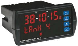
The PD6300 features a dual-line, 6-digit display, with optional Sunbright® LEDs for excellent visibility even in bright sunlight. The flow rate is shown on the top line, while the cumulative total appears on the bottom line. With its total overflow capability, it can display totals up to 9 digits, ensuring you never miss a reading.
Key features of the PD6300 include:
- UL / C-UL listing and CE marking for safety and compliance.
- NEMA 4X front for protection against dust and water.
- Flexible power options with AC or DC compatibility.
- Ability to add up to four internal relays for enhanced functionality.
- 4-20 mA output for easy integration with other systems.
- Modbus® RTU serial communications for seamless data transfer.
The PD6300 comes with a 24 VDC power supply to operate the flowmeter efficiently. You can easily program the device using the front panel pushbuttons or the free MeterView® Pro software, making setup a breeze.
Choose the Precision Digital PD6300 for reliable flow measurement and totalization, perfect for various applications in industrial settings.