The Loop Leader+ Loop-Powered Flow Rate/Totalizers with Advanced Display Features.
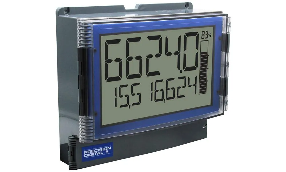
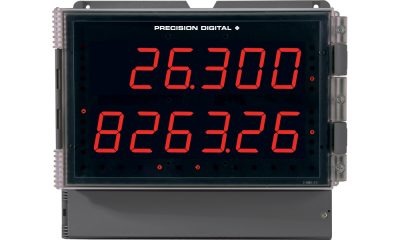
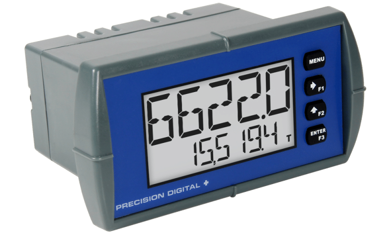
The Precision Digital Loop Leader+ flow rate/totalizer display offers a convenient and informative representation of any 4-20 mA signal through its loop-powered, large dual-line display. The top display is a 2.8″ 5-character alphanumeric line that shows flow rate, while the bottom line is a 1.5″ 8-character alphanumeric display, which can display flow total, grand total, or a tag. The 14-segment alphanumeric characters provide a clear representation of tags, units, and alarm messages.
In addition, the display also includes a 20-segment bargraph with a numeric value of the percentage representation. The meters can be programmed and set up using the free PC-based MeterView XL software that connects via micro USB cable.
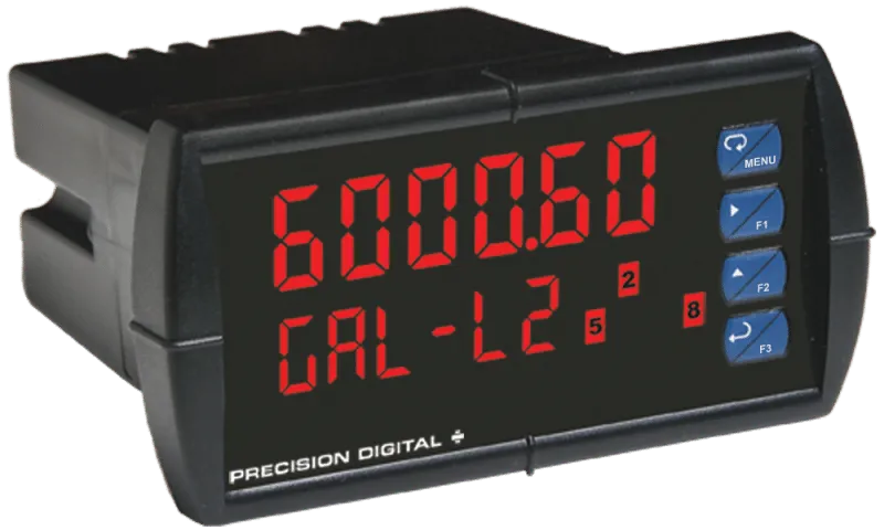
The PD4 comes in two configurations: display only and with two solid-state relays and 4-20 mA analog output. The devices also have two open collector outputs and remote contacts for alarm indication and pulse output, remote operation of programming buttons, resetting of the total, timer/stopwatch start/stop, and more. The relays can be programmed for alarm indication, sample, timer, batch control, and stopwatch.
For safe area versions of these instruments, click here.
Except where noted all specifications apply to operation at +25°C.
Display
| Display | Dual-line LCD with backlight.
Both lines 14-segment alphanumeric.
Top: 2.8″ (71 mm) 5 digits
Bottom: 1.5″ (39 mm) 8 characters
Display may be programmed to turn red and flash a user-defined message on alarm condition. |
| Top Display | 5 digits (-9999 to 99999) or 5 characters
(all capital & most lower-case letters) |
| Bottom Display | 8 digits (-9,999,999 to 99,999,999; separated by commas) or 8 characters
(all capital & most lower-case letters) |
| Backlight Power Requirement | 24 VDC @ 46 mA, typical |
| Bargraph | 20 segments, numeric percent indication at top |
| Decimal Point | Up to four decimal places on top display and up to seven decimal places on bottom display |
| Commas | Commas to indicate 1000s
(e.g. 88,987,628) on bottom display only |
| Dual-Scale Feature | The input can be displayed in different scales on the top and bottom displays. For instance, the top display could display the flow in GPM and the bottom display could display that same input in CFM. |
| Alarm Indication | Programmable: red backlight, flashing display, bargraph segment flashes on alarm. Backlight requires external 24 VDC. |
| Custom Alarm Messages | Programmable for each relay/open collector: 8 characters maximum; displayed every 10 sec for 1 sec on bottom display. May be turned off. |
| Display Update Rate | Ambient > -10°C: 1 Update/Second
Ambient = -20°C: 1 Update/2 Seconds
From -20°C to -40°C the update rate slows down
1 second for every -2°C (e.g. at -24°C, 1 update/4 seconds). |
| Overrange | Top: 99999
Bottom: 99,999,999 (flashing) |
| Underrange | Top: -9999
Bottom: -9,999,999 (flashing) |
General
| Programming Method | Buttons behind lower panel door & Free PC-based USB programming software |
| Enclosure & Materials | Material: High impact Polycarbonate with UV stabilizer enclosure, UL 94V-0
Rating: NEMA 4X / IP65
Gasket: Polyurethane
Color: gray
Includes four PG11 through-hole conduit openings, with two factory installed PG11, IP68, black nylon threaded hole plugs with backing nuts. |
| Environmental | Operating temperature range: -40 to 75°C (-40 to 167°F)
Storage temperature range: -40 to 85°C (-40 to 185°F)
Relative humidity: 0 to 90% non-condensing;
Printed circuit boards are conformally coated. |
| Noise Filter | Averages the input signal over a period of time between 1 and 16 seconds to dampen the effects of a noisy signal that causes a jumpy display. |
| Filter Bypass | 0.0 to 99.9% of full scale. Input signal changes greater than bypass value are displayed immediately. |
| Recalibration | Recalibration is recommended at least every 12 months. |
| Max/Min Display | Max/min readings reached by the process are stored until reset by the user or until power to the meter is turned off. |
| Tare | If the totalizer is disabled, the Tare function zeros out the meter to remove the weight of a container. Tare function can be assigned to a function key or the digital input. |
| Password | There are three separate passwords available that can be set independently of each other: Main, Total, and Grand Total.
The Main password prevents access to the meter Programming Mode.
Total and Grand Total passwords prevent resetting the total and grand total, respectively. |
| Non-Volatile Memory | Total and Grand Total values, and all programmed settings are stored in non-volatile memory for a minimum of ten years if power is lost. |
| Normal Mode Rejection | 64 dB at 50/60 Hz |
| Connections | Removable screw terminals accept 12 to 22 AWG wire.
Remote contacts accept 16 to 30 AWG wire. |
| Tightening Torque | Screw terminal connectors: 4.5 lb-in (0.5 Nm)
Mounting screws: 8.0 lb-in max. (0.9 Nm)
Remote contacts: 2.5 lb-in (0.28 Nm) |
| Overall Dimensions | 10.6″ x 12.6″ x 4.8″
(270 mm x 320 mm x 121 mm)
(H x W x D) |
| Weight | 5.5 lbs (2.5 kg) |
| Warranty | 3 years parts and labor. |
Input
| Input | 4-20 mA |
| Accuracy | ±0.02% of span ±1 count
Square root and programmable exponent: 10-100% FS |
| Voltage Drop | 2.1 V maximum |
| Equivalent Resistance | 105 Ω @ 20 mA |
| Input Overload | Over current protection to 1 A maximum, Over voltage protection to 30 VDC max (between mA+ and mA-/BL-) |
| Temperature Drift | 25 PPM/°C from -40 to 75°C ambient |
| Function | Linear (2-32 points), square root, or programmable exponent
PV2: Linear (2-32 points) or round horizontal tank (If total is disabled and PV2 is enabled) |
| Low-Flow Cutoff | 0.1 to 999,999 or disable. Point below at which the display always shows zero. |
| HART Transparency | The meter does not interfere with existing HART communications; it displays the 4-20 mA primary variable and it allows the HART communications to pass through without interruption.
The meter is not affected if a HART communicator is connected to the loop. The meter does not display secondary HART variables. |
Rate/Totalizer
| Rate Display | Top display: -9999 to 99999;
Bottom display: -9,999,999 to 99,999,999 (with commas) |
| Total & Grand Total Display | Top display: 0 to 99999;
Bottom display: 0 to 99,999,999 (with commas) |
| 13-Digit Total & Grand Total | Up to 9,999,999,999,999 using both lines with 13-digit total feature enabled. |
| Total Decimal Point | Up to four decimal places on top, up to seven decimal places on bottom. Total decimal point is independent of rate decimal point. |
| Totalizer | Calculates total based on rate and rate units to display total in engineering units. A custom factor must be programmed if using custom defined units. |
| Time Base | Seconds, Minutes, Hours, Days |
| Totalizer Rollover | Totalizer rolls over when display exceeds 99,999,999 (9,999,999,999,999 if 13-digit limit enabled). Relay status reflects display. |
| Total & Grand Total Reset | Via front panel button, external contact closure on digital input, or MeterView XL. |
| Total & Grand Total Reset Passwords | Total and grand total passwords may be entered to prevent resetting the total or grand total unless a password is entered. |
| Non-Resettable Grand Total | Grand total reset may be disabled through the meter interface. Grand total reset may be permanently disabled by selecting YES at the PERMLOCK menu. |
 |
| • Once the Grand Total has been programmed as “non-resettable” the feature CANNOT be disabled. |
| Non-Volatile Memory | Total and Grand Total values are stored in non-volatile memory for a minimum of ten years if power is lost. |
Batch Control
| Methods | Automatic or Manual, count up or count down |
| Manual Batch Start | Pressing F1 function key starts the batch |
| Manual Batch Pause/Stop | Pressing F3 once pauses the batch, pressing it twice cancels the batch |
| Automatic Batching | The Loop Leader+ can be used as an automatic batch controller where batches run continuously without operator input |
| Batching Relay Operation | Single or dual-relay batching with optional preclose for two-stage operation |
| Batch Preset | Set via F2 function key anywhere between 0.0001 to 99,999 based on batch total decimal point. If batch total is assigned to bottom, the preset can be up to 8 digits. |
| Batch Preclose | For two-stage batch application, a preclose value can be set to close the main flow line. |
| Automatic Batch Restart Delay | 1 to 9,999 seconds. The batch will automatically restart after completion of the last batch. |
Common Open Collector & Relay Specifications
| Number | Two open collectors & two relays |
| High or Low Alarm | User programmable for high or low alarm |
| Alarm Deadband | 0-100% FS, user programmable |
| Output Assignment | Alarm, Timer, Stopwatch, or Disable |
| Alarm Output Source | Assign to rate, total, grand total, or digital input |
| On & Off Time Delay | 0 to 9,999 seconds |
| Fail-Safe Operation | Independent for each open collector and relay.
Fail-safe on, the output is on under normal conditions.
Fail-safe off, the output is on under alarm conditions. |
| Alarm Operation | Automatic, automatic with manual override, latching (manual reset anytime), latching with reset after cleared (manual reset only after alarm has cleared) |
| Alarm Indication | Programmable: red backlight, flashing display, Bargraph segment flashes on alarm. Backlight requires external 24 VDC. |
| Custom Alarm Messages | Programmable for each relay/open collector: 8 characters maximum; displayed every 10 sec for 1 sec on bottom display. May be turned off. |
| Alarm Acknowledge | Front panel ACK button or external digital input resets output and screen indication. |
| Auto Initialization | When power is applied to the meter, open collectors and relays will reflect the state of the input to the meter. |
| Timer Output | One-shot or Continuous
Off Time Delay: 1 sec to 99:59:59 (hrs:min:sec)
On Time: 1 sec to 99:59:59 (hrs:min:sec) |
| Stopwatch | Output turns on when started and off when stopped. |
Open Collector Outputs
| Rating | Isolated open collector, sinking NPN
5-30 VDC @ 150 mA maximum |
| Output Assignment | Pulse, Alarm, Timer, Stopwatch on/off, or Disable |
| Pulse Output Source | Pulse output based on Rate, Total, Grand Total, or Test Frequency, Alarm, Timer, Total Reset, Stopwatch on/off, or Disable |
| Pulse Output Factor | 0.000001 to 999,999.9 |
| Pulse Width | 0.5 ms @ 1 kHz; 500 ms @ 1 Hz; 50% duty cycle |
| Pulse Output Frequency | 1,000 Hz maximum |
| Quadrature Pulse Output | Available for Output 2
(90° behind Output 1) 500 Hz max |
| Alarm Output Source | Assign to Rate, Total, Grand Total or Digital Input |
Solid-State Relays
| Rating | 250 VAC/VDC @ 1 A resistive
75 VA; 250VAC; 0.6 A pilot duty (inductive) – UL Code D300
25 VA; 250VDC; 0.6 A pilot duty (inductive) – UL Code R300 |
| Noise Suppression | Metal oxide varistors across outputs |
| Relay Assignment | Alarm, Sample, Timer, Batch, Stopwatch on/off, or Disable |
| Alarm Output Source | Assign to Rate, Total, Grand Total, or Digital Input |
| Relay Runtime | Meter will keep track of how long each relay has operated and display this information. |
| Relay Cycles | Meter will keep track of how many times the relays have cycled and display this information. |
4-20 mA Transmitter Output
| Accuracy | ±0.05% FS ±0.001mA |
| Output Source | Rate, total, re-transmit; reverse scaling allowed |
| Scaling Range | 1.00 to 23.0 mA |
| Disable | High impedance state, less than 1 mA |
| Calibration | Factory calibrated 4.00 to 20.00 mA |
| Underrange | 1.0 mA, 3.5 mA, or 3.8 mA (If input < 3.5 mA); or or Off; user selectable |
| Overrange | 20.5 mA, 20.8 mA, or 23.0 mA (If input > 20.5 mA); or Off; user selectable |
| Isolation | 500 V input-to-output |
| Temperature Drift | 0.5 μA/°C max from -40 to 75°C ambient |
| External Loop Power Supply | 7.0 VDC to 30.0 VDC maximum |
| Output Loop Resistance | 10-750 Ω @ 24 VDC; 10-1100 Ω @ 30 VDC |
On-Board Digital Input
| Function | Remote operation of front-panel buttons, acknowledge/reset relays, reset total, reset max/min values, etc. |
| Contacts | 2.1 VDC on contact. Connect normally open contacts across DI+ and DI- |
| Logic Levels | Logic High: 2.4 to 30 VDC (max)
Logic Low: 0 to 0.9 VDC |
Remote Contacts
| Function | Terminals provided for remote operation of all four programming / operation buttons (use PDA2364-MRUE control station). |
| Remote Buttons | Menu, Right, Up, Enter |
| Remote Function Keys | F1 / Reset*
F2 / Max*
F3 / Ack*
*Defaults |
MeterView XL Programming Software
| Availability | Free download from www.predig.com/meterviewxl |
| System Requirements | Microsoft® Windows® 7 & 10 |
| Communications | USB 2.0 (Standard USB A to USB B) Cable provided |
| Configuration | Configure all parameters on the meter. Configure meters one at a time. |
| Configuration Files | Generate with or without meter connected; Save to file for later use. |
| USB Power Connection | Meter is powered by USB connection during programming, if 4-20 mA loop is not connected. |
| Compatibility | Programs created for Loop Leader and Loop Leader+ may be run on either meter. Programs created for VantageView+ and ProtEX+ can be run on either meter. No other program sharing is permissible. |
General Compliance Information
Electromagnetic Compatibility
| EMC Emissions | • CFR 47 FCC Part 15 Subpart B Class A emissions requirements (USA)
• AS/NZS CISPR 11 Class A ISM emissions requirements (Australia)
• EN 55011 Group 1 Class A ISM emissions requirements (EU)
• ICES-001 Issue 4 ISM emissions requirements (Canada) |
| EMC Emissions and Immunity | EN 61326-1
EMC requirements for Electrical equipment for measurement, control, and laboratory use – industrial use |